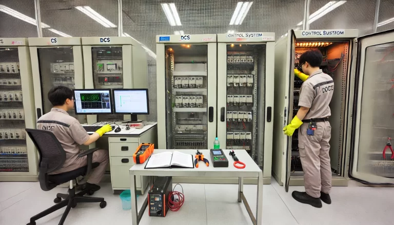
In a Distributed Control System (DCS), a deadband (also called hysteresis) is a designated range above and below an alarm setpoint. Within this range, small parameter fluctuations will not trigger an alarm, even if they approach the alarm limit. The deadband setting acts as a “no-alarm zone,” effectively preventing frequent alarms caused by minor, often inconsequential variations. This buffer is essential in enhancing the reliability and efficiency of DCS alarms, ensuring operators can focus on actual system issues rather than being distracted by constant false alarms.
In this combined article, we’ll examine the concept of deadband, its advantages, and provide guidelines on optimal deadband settings for various process parameters.

What is Deadband in a DCS System?
A deadband is an intentional buffer range set around an alarm limit to prevent frequent triggering due to small, normal fluctuations. By configuring a deadband, DCS systems avoid unnecessary alarm activations, allowing operators to focus on more significant deviations that may indicate true system anomalies. For instance, if the upper alarm for a temperature control point is set at 100°C and the lower alarm at 90°C, a 2°C deadband might be introduced. With this setting, minor fluctuations between 98°C and 102°C would not trigger an alarm, avoiding alerts due to minor environmental variations and thus improving overall system stability.

Key Benefits of Using Deadband in Alarms
Reducing False Alarms: Without a deadband, slight parameter variations near an alarm limit can repeatedly trigger alerts. Deadband settings reduce this, allowing the system to avoid signaling when only minor fluctuations are occurring, which are often insignificant.
Stabilizing System Operation: Frequent alarms disrupt operator focus, as they become accustomed to silencing minor alerts. Deadband prevents unnecessary interruptions, letting operators focus on meaningful anomalies and supporting smoother operations.
Improving System Responsiveness: By reducing excessive alarm triggers, DCS resources are better allocated to critical processes. This reduces the likelihood of system overload and improves the system’s responsiveness to actual anomalies.
Extending Equipment Lifespan: Repeated alarms can lead to constant equipment activation and shutdown, especially when alarm-triggered control actions occur. A deadband reduces this cycling, helping to preserve the lifespan of equipment and sensors.

Deadband Setting Recommendations for Various Parameters
Deadband settings vary depending on the parameter type, the system’s operational requirements, and the nature of fluctuations for each parameter. Below are guidelines on recommended deadband ranges for common parameters in DCS systems:
1. Temperature Parameters
- Recommended Deadband Range: 1°C to 5°C.
- Explanation: Temperature often changes slowly, with variations from environmental factors or minor inaccuracies in sensors. A deadband within this range allows the system to ignore these minor changes, focusing instead on real deviations from the setpoint.
2. Pressure Parameters
- Recommended Deadband Range: 1% to 3% of the full scale.
- Explanation: Pressure can change rapidly, especially in dynamic systems. A deadband of 1% to 3% effectively reduces alarm activations due to small, quick fluctuations that aren’t operationally critical.
3. Liquid Level Parameters
- Recommended Deadband Range: 1% to 5% of the full scale.
- Explanation: Liquid levels can vary due to external factors like vibration and temperature. A 1% to 5% deadband helps prevent minor level changes from triggering an alarm, reducing nuisance alarms while capturing significant level deviations.
4. Flow Parameters
- Recommended Deadband Range: 2% to 5% of the full scale.
- Explanation: Flow rates tend to vary during operational shifts, such as startup and shutdown phases. A deadband of 2% to 5% accommodates these normal changes, allowing operators to focus on substantial flow issues.
5. Rotational Speed Parameters
- Recommended Deadband Range: 0.5% to 2% of the range.
- Explanation: Rotational speeds can vary slightly due to load fluctuations. Setting a deadband in this range prevents alarms from being triggered by minor speed adjustments, maintaining focus on meaningful speed deviations.
6. Electrical Current and Voltage Parameters
- Recommended Deadband Range: 1% to 3% of the total range.
- Explanation: Electrical parameters are prone to quick shifts with load changes. A 1% to 3% deadband reduces alerts caused by these minor shifts, focusing alarms on more critical electrical fluctuations.
7. Chemical Parameters (pH Levels, Concentration)
- Recommended Deadband Range: 0.1 to 0.5 pH units or concentration units.
- Explanation: Small chemical changes often don’t impact process integrity, but pH and concentration are highly sensitive to environmental factors. This range prevents frequent alarms due to minor chemical shifts while ensuring any significant deviations are detected.
8. Miscellaneous Parameters (e.g., Vibration, Frequency)
- Recommended Deadband Range: 1% to 5% of the full range.
- Explanation: For parameters like vibration, a 1% to 5% deadband avoids alarms caused by regular, minor oscillations while still capturing significant mechanical issues.

Practical Considerations When Setting Deadbands
- Parameter Behavior: For parameters that change slowly (like temperature), a smaller deadband is often appropriate, whereas quickly fluctuating parameters (like flow) benefit from a larger deadband.
- System Stability: Stable systems may require a smaller deadband, as fluctuations are rare. In more dynamic systems, a larger deadband is often necessary to prevent alarm fatigue.
- Process Criticality: High-priority parameters that impact safety or product quality require tighter deadbands to catch slight deviations, while less critical parameters can tolerate wider deadbands.
- Environmental Conditions: Factors such as vibration, temperature changes, and load fluctuations affect readings. A deadband helps filter out alarms caused by these conditions, focusing attention on significant changes.

Conclusion
In DCS systems, setting a deadband for each alarmed parameter is crucial for effective alarm management. The deadband range provides a “no-alarm” zone that avoids unnecessary alarms from minor fluctuations. By tailoring deadband settings to the unique characteristics of each parameter, DCS systems can reduce false alarms, streamline operations, enhance response times, and extend equipment lifespan. Thoughtful deadband configuration is a key step in developing a stable, responsive, and manageable DCS system, ensuring that operators can focus on genuine system concerns rather than frequent minor alerts.
