1. Introduction
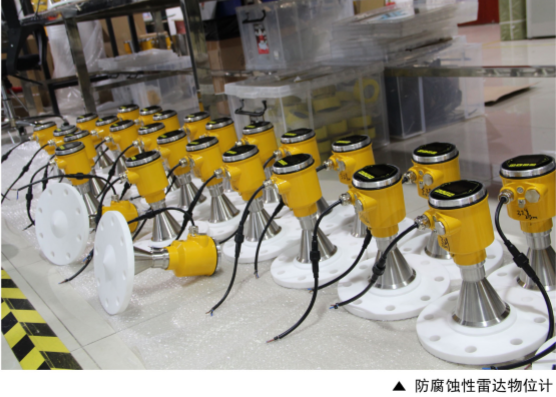
Radar level transmitters have become a preferred solution for level measurement in liquids, slurries, and solids due to their non-contact design, high accuracy, and wide application range. However, in challenging industrial environments—such as high-temperature steam chambers, dusty silos, or foam-prone tanks—various interferences may impact signal stability and measurement accuracy.
This article explores the physical principles behind radar wave propagation, identifies common interference sources in typical field scenarios, and proposes targeted solutions. The goal is to provide practical guidance for engineers and technicians during instrument selection, commissioning, and troubleshooting.
2. Understanding Common Interference in Radar Level Measurement
In real-world applications, radar level sensors may encounter several types of signal interference, typically including:
Steam and Condensation: High-temperature steam or humidity can attenuate microwave signals, reducing effective echo strength.
Dust Scattering: Particulate matter in silos or hoppers can reflect or scatter radar waves, leading to distorted echo patterns.
Foam and Bubbles: Surface bubbles or floating foam may cause false echoes, erratic level readings, or signal dropouts.
Each interference type originates from different physical mechanisms and requires specific countermeasures, which are discussed in the following sections.
3. Steam Interference: Signal Attenuation Mechanism and Solutions
3.1 Mechanism of Steam-Induced Attenuation
High-temperature steam environments, especially in tanks with continuous evaporation or boiling media, can significantly affect radar signal propagation. The primary issues include:
Microwave Absorption by Water Vapor: According to ITU-R P.676 attenuation models, water vapor has a strong absorption effect on electromagnetic waves, particularly in the K-band and W-band frequency ranges.
Condensation on the Antenna Surface: When radar antennas are mounted above boiling tanks, steam can condense and form water droplets on the antenna or radome. This causes scattering and damping of outgoing and returning signals.
Dielectric Constant Variation: Fluctuating humidity and temperature lead to changes in the dielectric constant of the transmission path, affecting signal velocity and echo intensity.
These effects may result in:
Weak or unstable echoes,
Sudden signal loss (false low level),
Measurement drift.
3.2 Recommended Solutions
To improve radar performance in steam-laden environments, the following measures are recommended:
Use Air Purge Systems: Install a dry air or instrument gas purge line to the radar antenna housing. Continuous purging prevents steam condensation on the antenna lens or horn.
Choose High-Frequency Models Carefully: While higher frequency radar (e.g., 80 GHz) offers narrower beam angles, it is more sensitive to vapor attenuation. For heavy steam environments, 26 GHz radar may provide more stable performance due to lower propagation loss.
Apply Antenna Heating or Insulation: Heating jackets or thermal insulation can maintain the antenna temperature above the dew point, preventing condensation.
Select Radar with Advanced Signal Processing: Devices equipped with dynamic echo tracking, vapor penetration compensation, and false echo suppression algorithms can better handle steam interference.
3.3 Application Notes
In steam environments such as reactors, digesters, or cooking tanks in the food and chemical industry:
Remote (Non-Integrated) Radar Designs are preferred to separate the electronics from high-temperature zones.
Guided Wave Radar (GWR) may be considered if condensation is severe, as the waveguide reduces energy dispersion and enhances stability in wet vapor spaces.

4. Dust Interference: Mie Scattering Effects and Suppression
4.1 Mechanism of Dust-Induced Interference
Dusty environments—such as cement silos, coal bunkers, grain storage, and fly ash hoppers—pose significant challenges to radar level measurement. The key interference mechanisms include:
Mie Scattering: When dust particle size is similar to the wavelength of the radar signal (e.g., 26 GHz ≈ 11 mm, 80 GHz ≈ 3.8 mm), electromagnetic waves are scattered according to Mie theory, leading to diffuse reflection and attenuation of the main echo signal.
Multi-Echo Reflection: Dust clouds generate numerous weak echoes that overlap with the true surface reflection, confusing the signal processing algorithm.
Dust Accumulation on the Antenna: Over time, fine powder may adhere to the antenna surface or radome, reducing signal transmission efficiency and stability.
As a result, radar level sensors in dusty conditions may experience:
Fluctuating or erratic readings,
False level indications (e.g., sudden drop or rise),
Signal loss during filling or material discharge.
4.2 Recommended Solutions
To ensure reliable radar performance in dusty process environments, the following countermeasures are recommended:
Select Radar with Narrow Beam Angle: High-frequency radar (such as 80 GHz) features a tighter beam (3–4°) that reduces contact with the tank walls and dust cloud, focusing energy directly on the material surface.
Apply Air Purge or Flushing Systems: A small purge of dry air prevents dust from settling on the antenna and maintains a clean transmission path.
Use Dust-Tolerant Antenna Designs: For example, lens antennas with sealed construction are less prone to dust adhesion than horn antennas.
Enable False Echo Learning: Most modern radar transmitters allow users to record and ignore fixed false echoes from dust-covered nozzles or internal structures.
Apply Advanced Filtering Algorithms: Signal processing technologies such as time-domain echo discrimination and dynamic gain control can effectively suppress scattered echoes.
4.3 Application Notes
In heavy dust environments, such as during silo filling or pneumatic conveying:
Top-mounting with waveguide extension may help radar penetrate the dust column and capture surface reflection.
Guided Wave Radar (GWR) is generally not recommended in dusty solids due to the risk of material build-up on the probe.
In outdoor silos:
Periodic maintenance (e.g., lens wiping or purging) is essential for sustained performance.

5. Foam and Bubble Interference: False Echoes and Signal Instability
5.1 Mechanism of Interference
Foam and surface bubbles are common in applications involving fermentation, wastewater treatment, chemical reactions, or surfactant-rich liquids. These conditions introduce unique challenges to radar level measurement due to:
Low Dielectric Constant of Foam: Foam consists mainly of gas trapped in thin liquid films, typically having a dielectric constant (εr) below 2. This results in very weak radar reflections and poor signal strength.
Irregular Surface Geometry: The bubble-covered surface presents a diffuse, uneven interface that scatters radar signals in multiple directions, reducing echo intensity and increasing measurement noise.
Multi-Path Reflection: Radar signals may reflect off the tank wall, internal structures, or the foam layer itself, leading to false echoes and inaccurate level readings.
Dynamic Surface Fluctuations: Foam height often fluctuates due to agitation or aeration, causing the radar to “chase” a moving echo instead of the actual liquid surface.
These effects can result in:
Unstable or drifting level readings,
Sudden level dropouts,
False high or low alarms.
5.2 Recommended Solutions
To mitigate the impact of foam and bubbles on radar performance, consider the following strategies:
Use Low-Frequency Radar (e.g., 6–26 GHz): Lower frequencies penetrate foam layers more effectively than high-frequency signals, making them more suitable for aerated or foaming liquids.
Enable Surface Tracking Mode: Many modern radar transmitters include algorithms to detect and track weak echoes beneath foam layers. These can improve measurement stability under frothy conditions.
Apply Filtering and Damping Settings: Increase damping time or enable echo averaging to smooth out rapid level fluctuations caused by foam motion.
Position Radar Away from Inlets or Aerators: Mount the sensor away from zones of turbulence or gas injection to minimize bubble interference.
Use a Still-Pipe or Bypass Chamber: In extreme foaming applications, installing the radar in a stilling well or bypass tube isolates it from foam effects and provides a stable reference surface.
5.3 Application Notes
In applications such as:
Bioreactors, fermenters, or anaerobic digesters: Radar units with foam-penetration capability and adjustable gain control are highly recommended.
Oil-water separation tanks or DAF systems: Radar may have difficulty distinguishing between foam, oil layer, and water interface—consider using interface radar or capacitance-based level sensors.
6. Field Case Studies: Interference Diagnosis and Correction
Case 1: Steam-Induced Signal Loss in a Boiling Tank
Application:
A radar level transmitter was installed on a high-temperature reaction vessel used for continuous boiling of a chemical solution. Operators reported frequent signal loss and erratic level readings during production.
Observed Symptoms:
Sudden drop to zero reading during steady operation
Weak or missing echo signals during steaming
Sensor recovered after vessel cooling
Diagnosis:
Analysis revealed that:
The antenna was located directly above the vapor outlet.
High-pressure saturated steam was condensing on the antenna surface, severely attenuating the radar signal.
No purge or heating device was installed on the antenna assembly.
Solution:
Installed a dry air purge system connected to the radar horn to prevent condensation.
Enabled steam compensation mode in the radar software.
Moved the mounting nozzle slightly off-center to reduce direct steam impingement.
Result:
The signal remained stable even under continuous boiling. Level control accuracy improved significantly, with no further false alarms.
Case 2: Dust Scattering in a Cement Silo
Application:
A high-frequency (80 GHz) radar sensor was deployed on top of a 30-meter cement silo for continuous level monitoring.
Observed Symptoms:
Erratic level readings during material filling
Sudden “full level” alarms when the silo was only 50% filled
Gradual signal degradation over several weeks
Diagnosis:
Mie scattering from dense airborne dust during pneumatic filling was overwhelming the echo processor.
Cement powder had accumulated on the radar lens, further degrading signal quality.
Echo curve showed multiple overlapping false echoes.
Solution:
Switched to a 26 GHz radar with a wider beam angle and better dust penetration.
Installed a compressed air purge kit for the antenna lens.
Adjusted the sensor’s false echo suppression profile based on actual fill patterns.
Result:
Level readings became stable and reliable, even during rapid filling. Maintenance intervals for lens cleaning were significantly reduced.
Lessons Learned:
These cases highlight the importance of:
Matching radar frequency to the application environment,
Using mechanical protection or purge systems in harsh conditions,
Leveraging advanced configuration features like echo mapping, damping, and suppression.

7. Conclusion: Optimizing Radar Performance in Complex Conditions
Radar level transmitters are highly versatile instruments, widely used across industries due to their non-contact operation, adaptability to various media, and high accuracy. However, their performance can be significantly affected by environmental interferences such as steam, dust, and foam.
This article has examined three of the most common and challenging interference scenarios:
Steam environments, where signal attenuation and condensation require active purge systems and strategic antenna placement.
Dusty silos, where Mie scattering and material buildup necessitate frequency selection and echo filtering.
Foamy or aerated surfaces, where weak reflections demand specialized signal processing and possibly low-frequency radar technology.
Through analysis of wave propagation theory and real-world application cases, we’ve outlined effective mitigation strategies to maintain reliable measurements even in extreme conditions.
Key Takeaways:
Proper selection of radar frequency is crucial—lower frequencies tend to perform better in vapor and foam, while higher frequencies offer tighter focus in confined spaces.
Mechanical and software-level adaptations (e.g., purging, echo suppression, advanced algorithms) can dramatically improve signal stability.
Regular maintenance and commissioning practices, such as antenna cleaning, false echo learning, and damping tuning, are essential to long-term reliability.
By understanding the root causes of interference and implementing the appropriate countermeasures, users can maximize radar measurement performance, reduce downtime, and ensure safer and more efficient process control.