In industrial maintenance, instrument technicians often face the dilemma of using a high-precision multimeter but struggling to accurately determine the temperature or check the health of resistance thermometers (RTDs) and thermocouples. Why can’t we get the correct temperature even after measuring the resistance? Why does the millivolt reading from the thermocouple never match the actual temperature? Is it the instrument’s fault, or is there a misunderstanding in the method? The truth is, with a clear understanding of the core principles and a few key calculation tricks, you can quickly estimate temperatures and troubleshoot faults using just a multimeter. This article avoids complicated theories and focuses on the most practical methods and techniques for the field, helping you work more efficiently and solve problems faster.

Core Principles: Understanding the Basics
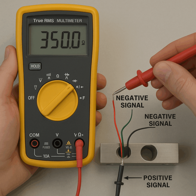
Resistance Temperature Detectors (RTD) – Using the example of the most common Pt100:
Principle: The resistance of platinum increases steadily with temperature. At 0°C, the resistance is 100Ω, and for every 1°C change, the resistance changes by approximately 0.385Ω.
Multimeter Measurement: Resistance (Ω).
Thermocouples – Using the example of the most common K-type:
Principle: Two different materials form a circuit at the measurement (hot) junction and the reference (cold) junction. A temperature difference between these junctions produces a thermoelectric voltage.
Key Point: The thermoelectric voltage reflects the temperature difference between the measurement and reference junctions. The multimeter measures the millivolt (mV) value.
Cold Junction Compensation: To obtain the actual temperature at the measurement point, you must know the temperature of the reference junction. The multimeter probes themselves act as the reference.

Quick Calculation Methods and Techniques for RTD (Pt100)
Method 1: Formula Estimation (Most Common and Fastest)
This method is the most practical in the field, based on the excellent linearity of Pt100 within the 0-100°C range.
Core Formula:
Temperature (°C) ≈ (Measured Resistance – 100) / 0.385
Tips and Application:
Quick Mental Calculation: Memorize the key coefficient 0.385.
Steps: Measure the resistance, subtract 100, then divide by 0.4 (for ease of mental calculation, 0.4 is used as an approximation for 0.385). The result is very close to the actual temperature.
Graduated Value Memory: Memorize key points for interpolation.
0°C → 100Ω
100°C → 138.5Ω
200°C → 175.86Ω
Example:
Measured resistance = 115Ω
115 – 100 = 15 → 15 / 0.4 ≈ 37.5°C (Actual calculation: 15 / 0.385 ≈ 39.0°C). This estimate is sufficient for quick judgment.
Method 2: Table Method (Most Accurate)
For precise values or wider temperature ranges, use the Pt100 resistance-temperature table.
Tips:
Keep a photo of the table on your phone or print a small card to carry.
DCS or PLC configuration software often has a standard function block for looking up the table.
On-Site Practical Tips:
Wire Configuration Impact:
Two-Wire: The measurement includes lead resistance, causing greater error. For a quick estimate, subtract about 0.5-2Ω for each lead.
Three-Wire: Most common. Measure the resistance between two leads (A-B, A-C). If they are equal, the leads are good and the measurement is accurate.
Four-Wire: The multimeter directly measures the precise resistance, no need to consider lead resistance.
Quick Fault Diagnosis:
A Pt100 sensor at room temperature (≈25°C) should show resistance between 109-110Ω.
Resistance readings significantly higher or lower may indicate an open circuit or short.
Quick Calculation Methods and Techniques for Thermocouples (K-Type)
Thermocouple calculations are more dependent on “tables” due to their severe non-linearity. However, we can learn quick estimation and judgment techniques.
Method 1: Approximation Method (For Rough Estimates)
For the K-type thermocouple in the 0-100°C range, the output voltage is approximately 0.04mV/°C.
Core Formula:
Temperature Difference (°C) ≈ Measured mV / 0.04
Tips and Application:
Combine with Cold Junction Temperature: Actual temperature = (Measured mV / 0.04) + Current Ambient Temperature.
Example:
If a K-type thermocouple outputs 2.0mV and the cold junction temperature is 25°C:
Temperature Difference ≈ 2.0 / 0.04 = 50°C
Actual Measurement Temperature ≈ 50 + 25 = 75°C
This is a rough estimate, but it’s useful in the field to quickly determine if a temperature is within a reasonable range.
Method 2: Table Method (Standard and Accurate)
This is the most accurate method. The steps are as follows:
Measure the mV value (E_mv) from the thermocouple using the multimeter.
Measure the reference temperature (T_ref) at the multimeter’s terminal using another thermometer or the temperature setting on the multimeter.
Use the K-type thermocouple table to look up the corresponding mV value (E_ref) for the cold junction temperature (T_ref).
Add the measured millivolt value (E_mv) and the reference value (E_ref) to get the total thermoelectric voltage (E_total).
Look up E_total in the K-type table to find the actual temperature.
Example:
Cold Junction Temperature (T_ref) = 25°C → E_ref ≈ 1.000mV
Measured E_mv = 20.0mV → E_total = 20.0 + 1.0 = 21.0mV
From the K-type table, E_total = 21.0mV corresponds to a temperature of approximately 506°C.
Practical Tips and Considerations:
Cold Junction Compensation is Crucial: When using a multimeter instead of a dedicated temperature instrument, never overlook the cold junction temperature, as it can drastically affect the reading.
Quick Fault Diagnosis:
Short-Circuit Test: Short the thermocouple wires, and the multimeter reading should quickly rise to the current ambient temperature’s corresponding mV value. If there’s no change, the circuit may be open.
Heating Test: Lightly heat the measurement end with a lighter or heat gun; the mV reading should significantly increase. If there’s no change or the reading is reversed, the thermocouple’s polarity may be reversed or it could be damaged.
Normal Values: At room temperature, a functional thermocouple will output a small mV, usually just a fraction of a millivolt. Readings of tens of millivolts with no apparent temperature change may indicate incorrect thermocouple type or wiring issues.

Quick Reference and Action Guide
Store Pt100 and K-type thermocouple tables in your phone for fast access.
Always record the ambient temperature when measuring a thermocouple.
Compare the quick measurements with DCS/PLC display values to check if the system is functioning normally, considering factors like wire loss and cold junction compensation.
Safety First: Always follow safety protocols when working near energized or high-temperature equipment.
Mastering these methods and techniques will help you efficiently troubleshoot temperature instruments in complex industrial environments, making you a highly effective “equipment doctor.”