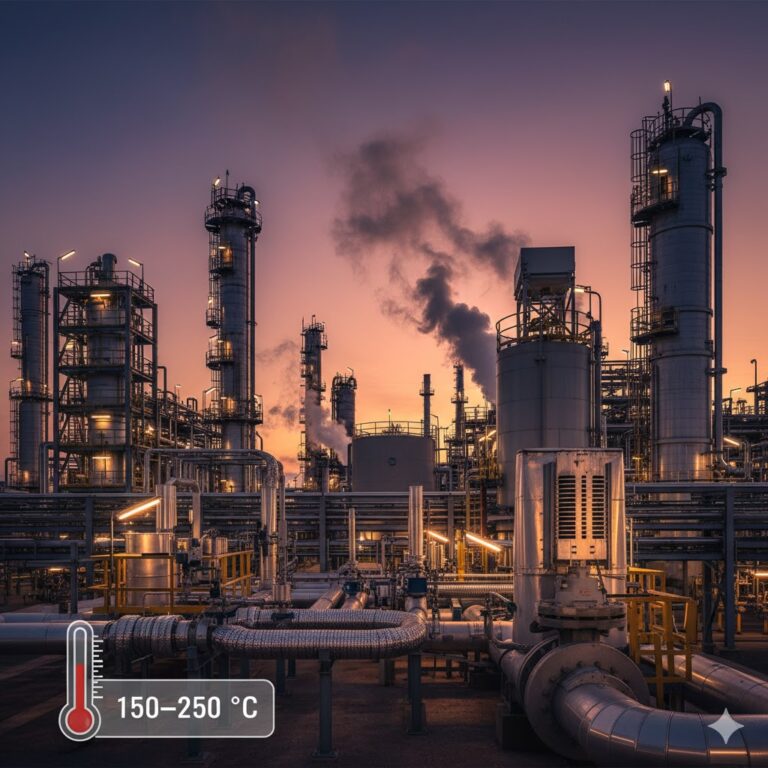
In chemical and process industries, instrumentation often operates under challenging high-temperature conditions — such as medium-pressure steam, thermal oil, or crystallizing process fluids. These environments demand not only reliable measurement and control performance but also effective thermal management. Temperature, pressure, and level instruments must remain accurate, while their electronic components stay within safe limits.
This article provides a comprehensive overview of insulation design, heat dissipation strategies, installation standards, and best practices for process instruments operating between 150–250 °C, helping engineers maintain both safety and reliability in high-temperature systems.
1. Thermal Challenges for Instruments in High-Temperature Environments
Common instruments in high-temperature process areas include:
RTDs (Pt100 / Pt1000): Used in heat exchangers, reactors, and pipelines.
Pressure transmitters: Measure the pressure of hot fluids or steam, often through impulse lines or remote seals.
Level transmitters (DP, radar, or magnetic type): Monitor tank or reactor levels under high process temperatures.
Control valves: Regulate the flow and pressure of hot media, often with temperature-sensitive actuators.
Key Insulation Requirements
Depending on the temperature range (150–250 °C) and the instrument’s configuration, insulation is typically required for:
Sensor or probe section: To prevent crystallization or solidification of viscous or salt-containing media at cooler points.
Impulse or capillary lines: To minimize measurement error due to thermal gradients.
Instrument housing: To protect electronic modules from radiant heat if no built-in cooling structure is provided.
Valve actuators: To avoid overheating of electric or pneumatic actuators when exposed to radiant or conducted heat.
Typical Conflicts Between Insulation and Cooling Needs
Electronics overheating vs. process insulation needs:
Electronic modules generally operate below +85 °C. Over-insulation can trap heat and shorten component lifespan.Anti-crystallization vs. heat dissipation:
For crystallizing media, insulation or trace heating is essential; yet excessive heat around sensors may degrade accuracy or materials.Actuator protection vs. ventilation:
Insulating control valves entirely may block ventilation paths, causing actuator malfunction or delayed response.

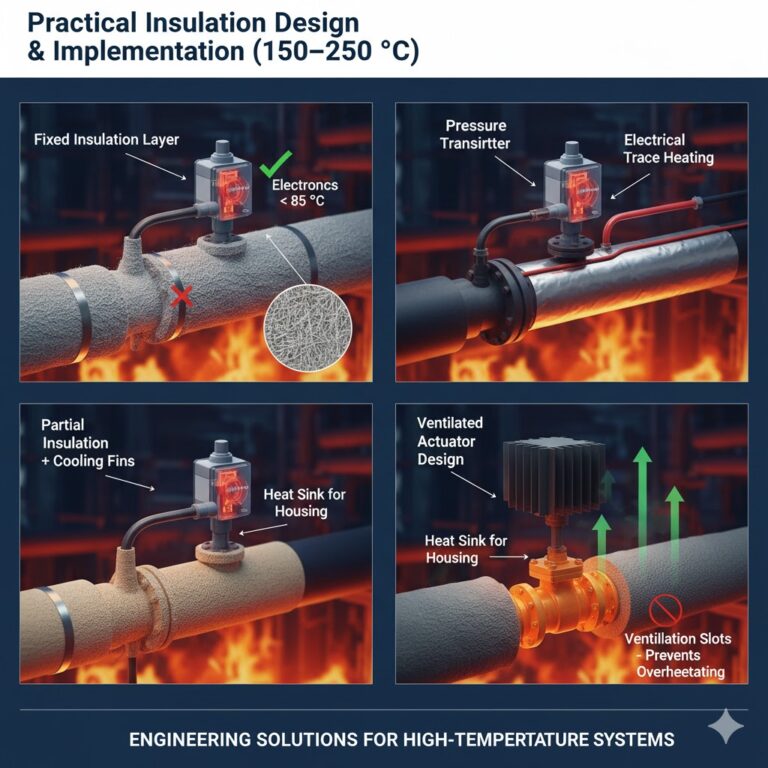
2. Practical Insulation Design and Implementation
Insulation strategies should align with the instrument structure and temperature tolerance of each component.
Common Insulation Methods
| Method | Description | Typical Application |
|---|---|---|
| Fixed insulation layer | Wrapped with ceramic fiber, glass wool, or aluminum silicate blanket | Static instruments (RTDs, transmitters) |
| Electrical or steam trace heating | Maintains medium fluidity and prevents crystallization | DP level transmitters, viscous fluids |
| Partial insulation + cooling combination | Local insulation for sensor areas; heat sink for housing | Transmitters with built-in fins |
| Ventilated or shielded actuator design | Adds ventilation holes or reflective covers | Control valves and actuators |
Recommended Materials (150–250 °C Range)
Aluminum silicate fiber blanket: Withstands >400 °C; lightweight and durable.
Glass wool insulation tube: Effective from −200 °C to +450 °C; ideal for impulse lines.
Ceramic fiber jacket: High mechanical strength and reusability for sensor assemblies.
Calcium silicate board: Good for housing insulation; requires moisture protection.
Determining Insulation Thickness
The insulation thickness should be defined by:
Temperature differential: Larger ΔT → thicker insulation.
Component heat tolerance: Internal temperature must remain below 85 °C for electronic modules.
Safety & process requirements: Crystallization-prone zones must maintain liquid flow.
Recommended Insulation Range by Instrument Type
| Instrument | Insulation Scope | Caution |
|---|---|---|
| RTD / Thermocouple | Insulate probe and neck; avoid over-insulating head | Monitor internal temperature |
| Pressure Transmitter | Insulate impulse lines; leave housing open for ventilation | Do not block heat fins |
| DP Level Transmitter | Insulate sensor and impulse tubing | Maintain consistent temperature |
| Radar Level Transmitter | Normally no insulation; optional anti-condensation heating | Avoid signal interference |
| Magnetic Level Gauge | Insulate main body if exposed to low temperature | Use nonflammable materials |
| Control Valve | Insulate valve body; keep actuator uninsulated or vented | Ensure explosion-proof ventilation |
3. Insulation Design in Explosion-Proof Zones (Ex d / Ex e)
In hazardous areas, insulation must not compromise explosion protection or introduce new ignition risks.
Safety Design Principles
Ex d (Flameproof enclosure):
The enclosure must remain sealed; insulation material must not obstruct joints or introduce combustible gases.Ex e (Increased safety):
Surface temperature must stay within certified limits (e.g., T4 ≤ 135 °C, T3 ≤ 200 °C). Insulation must not raise surface temperature beyond classification.
Material Requirements
Use nonflammable and non-toxic insulation materials complying with IEC 60079-0 or GB 3836.1.
Avoid organic binders that release gas when heated.
Maintain electrical grounding and mechanical integrity after insulation installation.
Surface Temperature Control
Thermal calculations or infrared temperature checks should confirm that:
If no heat sink is available, minimize insulation thickness to prevent excessive enclosure temperature.

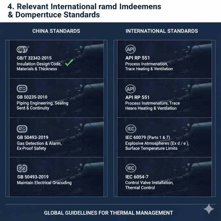
4. Relevant International and Domestic Standards
China Standards (GB/T Series)
GB/T 32342-2015 – Instrumentation Insulation Design Code
Defines insulation materials, thickness calculation, and installation methods.GB 50235-2010 – Piping Engineering Code
Covers continuity and sealing requirements for impulse line insulation.GB 50493-2019 – Gas Detection and Alarm Design
Specifies safety controls for explosion-proof instruments with insulation.
International Standards
API RP 551 – Process Instrumentation
Recommends trace heating and actuator ventilation under high-temperature conditions.IEC 60079-1 / IEC 60079-7 – Explosive Atmospheres (Ex d / Ex e)
Defines maximum surface temperature, housing material, and installation limits.IEC 60534-7 – Control Valve Installation and Maintenance
Provides guidelines for valve body temperature control and installation layout.
5. Engineering Design Formula
For determining required insulation thickness, the following simplified thermal balance can be used:
Where:
Q = Heat loss (W)
k = Thermal conductivity of insulation (W/m·K)
L = Pipe length (m)
T₁, T₂ = Medium and ambient temperature (°C)
r₁, r₂ = Inner and outer radii (m)
By setting an acceptable heat loss, the required thickness r₂ − r₁ can be derived.
6. Best Practices for Implementation
Step-by-Step Design Process
Identify instrument type and location:
Determine whether it’s a transmitter, sensor, or control device, and check if it’s in an explosion-proof area.Assess insulation and overheating risks:
Compare process temperature, ambient temperature, and component limits.Select appropriate insulation materials and thickness:
Apply thermal calculations according to GB/T 32342 or API RP 551.Verify explosion safety:
Ensure material compliance with IEC 60079 and maintain grounding continuity.Monitor and maintain:
Periodically check surface temperatures and replace aged insulation.
Recommended Maintenance Practices
Install temperature sensors inside housings for real-time monitoring.
Inspect insulation layers regularly for cracking, moisture absorption, or loosening.
Keep ventilation holes unobstructed in control valves and transmitters.
Record surface temperatures periodically to ensure compliance with Ex classification.

7. Key Takeaways
Balance is essential:
Protect sensors against crystallization while keeping electronics cool.Customize insulation:
Adapt strategy per instrument type, mounting position, and process medium.Follow standards:
GB/T 32342, API RP 551, and IEC 60079 provide solid design frameworks.Maintain regularly:
Degraded insulation leads to inaccurate readings and safety hazards.

Conclusion
In high-temperature process environments, instrument insulation is not just about keeping heat in — it’s about maintaining measurement accuracy, electronic stability, and explosion safety simultaneously.
By adopting differentiated insulation strategies, selecting nonflammable materials, and implementing regular temperature monitoring, engineers can achieve a robust balance between thermal protection and reliable measurement.
Well-designed insulation systems ultimately extend instrument service life, reduce maintenance frequency, and ensure process safety — achieving both efficiency and reliability in demanding industrial applications.